2024.03.01
Precision Gear Measurement Technology: Application and Analysis of Gear Measuring Systems (A Case Study of the KLINGELNBERG P26)
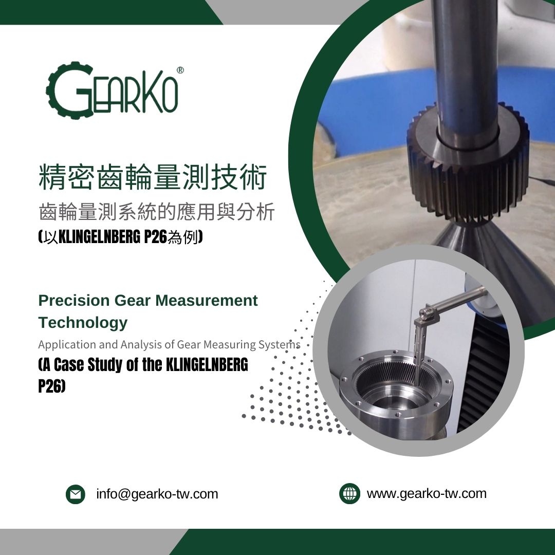
Our company’s inspection of all gears within planetary reducers utilizes the highly recognized KLINGELNBERG P26 Gear Measuring Center, a high-precision automatic gear measuring instrument, as shown in Figure 1. Application measurement examples are provided in Figures 2-3. This gear measuring instrument is capable of measuring the profile errors (PROFILE), lead errors (LEAD), individual pitch errors (fp) on both left and right tooth surfaces, cumulative pitch errors (Fp) on both left and right tooth surfaces, total pitch errors (fu), runout errors (Fr), and tooth thickness variation (Rs) for both spur and helical gears. It automatically determines the DIN gear evaluation to which the measurement belongs, with a measurement error precision of 0.0015mm. After measuring, it automatically generates data reports in the format shown in Figures 4-5. The following will explain the interpretation of the report content.
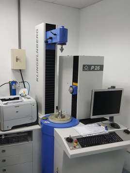
Figure 1 Gear Measuring Instrument
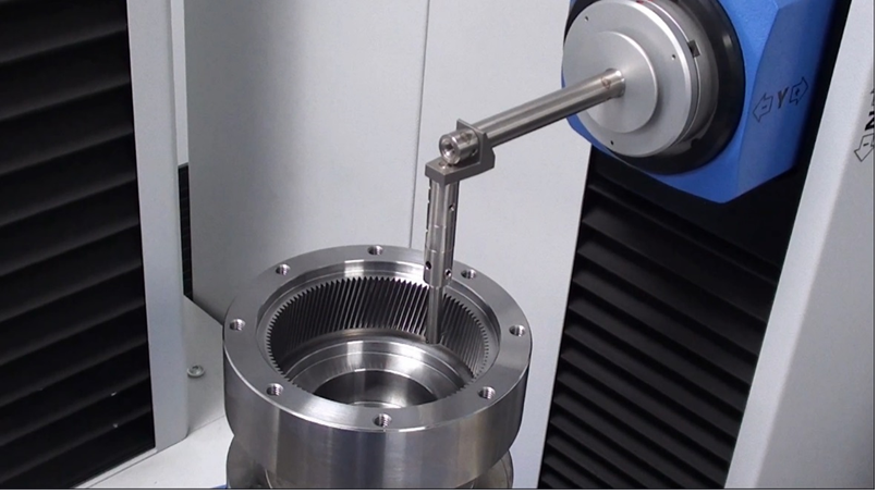
Figure 2 Gear Measuring Instrument Measuring Internal Gears
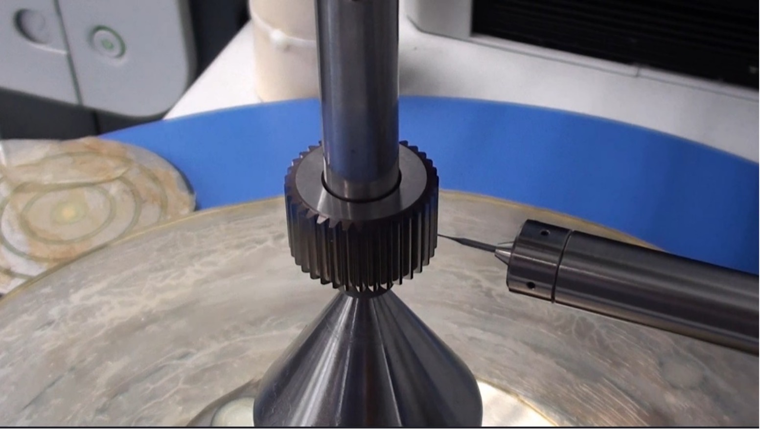
Figure 3 Gear Measuring Instrument Measuring External Gears
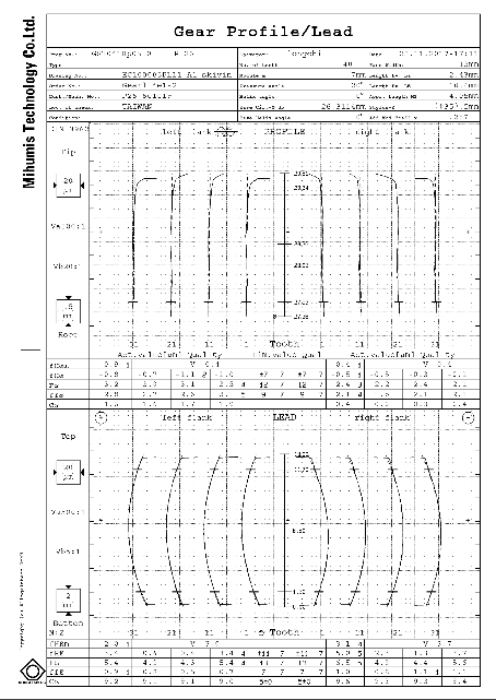
Figure 4 Gear Measuring Instrument Report Front Page
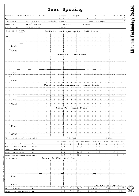
Figure 5 Gear Measuring Instrument Report Back Page
The analysis report content is explained with reference to the profile error chart 6. The numerical evaluation is expressed in micrometers (µm), and the evaluation level standard is set to DIN 7 according to DIN 3962. The report details are divided into left tooth surface profile and right tooth surface profile. "A" represents the evaluation length. The terms are defined as follows: fHαm for the average profile deviation, fHα for the profile angle deviation, Fα for the cumulative profile deviation, ffα for the profile shape deviation, and Cα for the profile deviation, as shown in table 1.
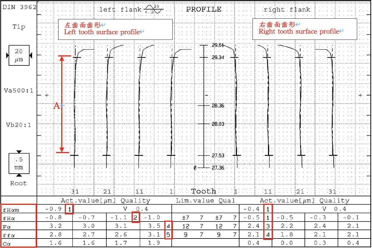
Figure 6 Profile Error Chart
Table 1 Profile Error Evaluation Chart
|
Content Evaluation |
Left Tooth Surface Profile Level |
Right Tooth Surface Profile Level |
|
fHαm (Average Profile) |
DIN 1 |
DIN 1 |
|
fHα (Profile Angle Error) |
DIN 2 |
DIN 1 |
|
Fα (Cumulative Profile Error) |
DIN 4 |
DIN 3 |
|
ffα (Profile Shape Error) |
DIN 5 |
DIN 4 |
The analysis report is explained based on the lead error chart 7, with numerical evaluation units in micrometers (µm). The evaluation level standard is set to DIN 7 according to DIN3962. The report details are divided into left tooth surface lead and right tooth surface lead. "B" represents the evaluation length. The terms are as follows: fHβm for the average lead value, fHβ for the lead angle deviation, Fβ for the cumulative lead deviation, ffβ for the lead shape deviation, and Cβ for the width barrel deviation, as shown in table 2.
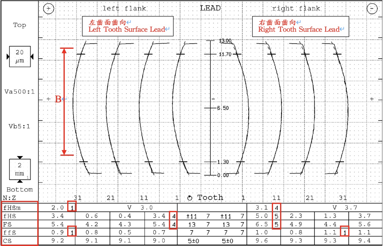
Figure 7 Lead Error Chart
Table 2 Lead Error Evaluation Chart
|
Content Evaluation |
Left Tooth Surface Lead Level |
Right Tooth Surface Lead Level |
|
fHβm (Average Lead) |
DIN 1 |
DIN 4 |
|
fHβ (Lead Angle Error) |
DIN 4 |
DIN 5 |
|
Fβ (Cumulative Lead Error) |
DIN 4 |
DIN 5 |
|
ffβ (Lead Shape Erro) |
DIN 1 |
DIN 1 |
The analysis report is explained based on the individual and total cumulative errors of the left and right tooth pitch, as shown in Figure 8. The numerical evaluation units are in micrometers (µm), and the evaluation level standard is set to DIN 7 according to DIN3962. The report content is divided into individual pitch error for left tooth, individual pitch error for right tooth, cumulative pitch error for left tooth, and cumulative pitch error for right tooth. The terms are as follows: fp max for individual pitch error, fu max for pitch error, Rp for pitch error range, Fp for total cumulative pitch error, and Fpz/8 for segment pitch error, as detailed in table 3.
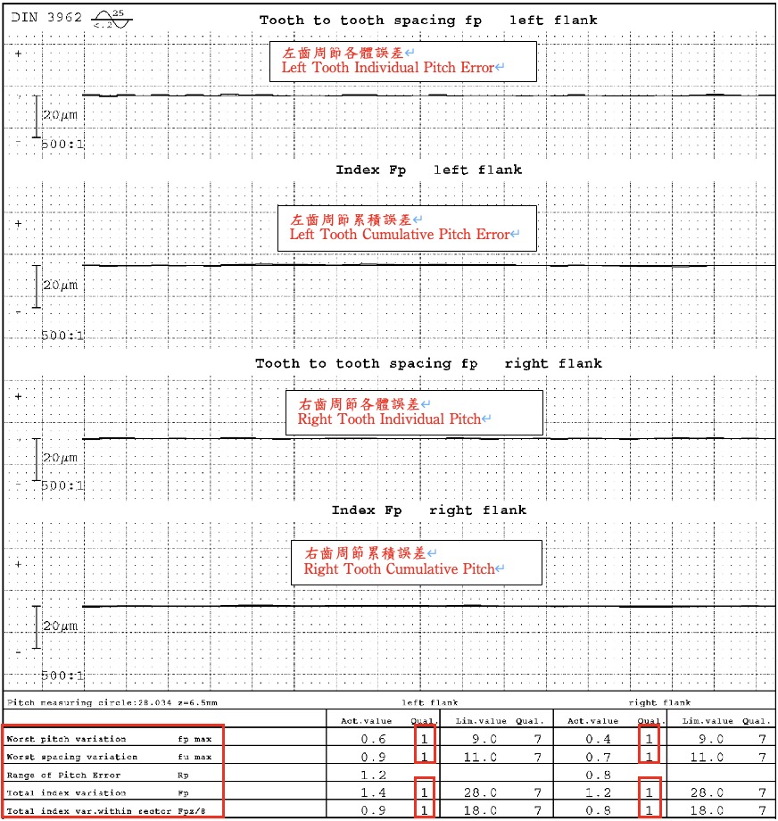
Figure 8 Left and Right Tooth Surface Individual Pitch (fp) and Total Cumulative Error (Fp) Chart
Table 3 Pitch Error Evaluation Chart
|
Content Evaluation |
Left Tooth Surface Lead Level |
Right Tooth Surface Lead Level |
|
fp max (Individual Pitch Error) |
DIN 1 |
DIN 4 |
|
fu max (Pitch Error) |
DIN 1 |
DIN 1 |
|
Fp (Cumulative Pitch Error) |
DIN 1 |
DIN 1 |
|
Fpz/8 (Segment Pitch Error) |
DIN 1 |
DIN 1 |
The analysis report content is based on the radial runout error (Fr) and tooth thickness variation (Rs) as shown in Figure 9. The numerical evaluation units are in micrometers (µm), and the evaluation level standard is set to DIN 7 according to DIN3962. The radial runout error (Fr) and the tooth thickness variation (Rs) are evaluated as DIN 1 level.
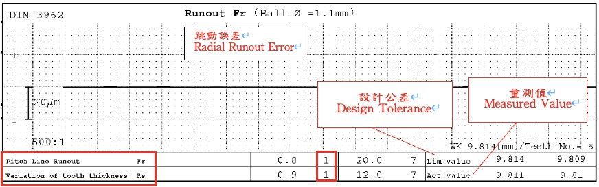
Figure 9 Radial Runout Error (Fr) and Tooth Thickness Variation (Rs) Chart
Gears are indispensable core components in planetary gearboxes, significantly affecting the performance and lifespan of the entire machinery. GearKo Taiwan understands this importance deeply, hence we invest considerable effort in gear inspection, adhering to the strictest international standards for quality review. Our expert team, with its rich experience and professional knowledge, can precisely control every detail of our products, ensuring that each planetary gearbox leaving our factory meets the highest quality standards. We proudly claim that through our rigorous testing processes and meticulous manufacturing techniques, we can offer our customers industry-leading, high-quality planetary gearboxes. If you have any needs regarding our products or services, please do not hesitate to contact us. We will provide the most professional consultation and attentive customer service.