2023.08.11
Planetary Reducer Selection Guide: Complete Analysis of 14 steps

Whether imported or domestically produced, planetary gear reducers have their own naming conventions, performance data, and dimensions for output and input interfaces by various manufacturers. Therefore, it is best to first consult the catalogs of planetary gear reducers from different manufacturers, and then select and design according to the catalogs.
|
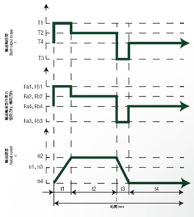
Operation Cycle |
Rotational Speed (r/min) |
Time (sec) |
Output Torque (Nm) |
Output Shaft Bearing Load (N) |
|
|
Radial Force |
Axial Force |
||||
|
Acceleration time |
n1 |
t1 |
T1 |
Fa1 |
Fb1 |
|
Constant time |
n2 |
t2 |
T2 |
Fa2 |
Fb2 |
|
Deceleratrion time |
n3 |
t3 |
T3 |
Fa3 |
Fb3 |
|
Pause time |
n4 |
t4 |
T4 |
Fa4 |
Fb4 |
Step 1:
(1) Load Operation Cycle ED = (t1 + t2 + t3) / t x 100%
(2) Cycle Time t = t1 + t2 + t3 + t4
- Periodic Operation: ED(1) < 60%, Total Cycle Time t(2) < 20 mins.
- Continuous Operation: ED(1) ≥ 60%, Total Cycle Time t(2) ≥ 20 mins. (Motor output torque can only use rated torque)
Step 2: Calculate the Reduction Ratio (i):
i = Motor Output Speed / Gear Reducer Output Shaft Speed (Actual Maximum Speed)
Step 3: Calculate the Average Torque at the Output End (T2m)
- T2m= ³√[(n1xt1xT13+n2xt2xT23+n3xt3xT33)/(n1xt1+n2xt2+n3xt3)]
Step 4: Calculate the Maximum Torque at the Output End (T2max): (If operating continuously, only the rated torque of the motor output can be used)
T2max = Motor's Maximum Output Torque × Reduction Ratio × Transmission Efficiency × Load Factor (η), where Load Factor (η) is defined as the number of cycles per hour.
1, 0~1000
1.1, 1000~1500
1.3, 1500~2000
1.6, 2000~3000
1.8, 3000~5000
Step 5: Look up the Gear Reducer's Rated Torque (T1) and Maximum Acceleration Torque (T4):
- Refer to the performance data sheets from various manufacturers; the following example refers to the GearKo performance data sheet.
Step 6:
Compare T2m with T1 Gear Reducer’s Rated Torque, and T2max with T4 Gear Reducer’s Maximum Acceleration Torque:
- When T2m < T1 and T2max < T4, the choice of gear reducer is correct.
- When T2m ≥ T1 or T2max ≥ T4, reselect a larger gear reducer.
Step 7: Calculate the Average Output Shaft Speed (S3): S3 = (n1 x t1 + n2 x t2 + n3 x t3) / (t1 + t2 + t3)
Step 8: Calculate the Rated Output Shaft Speed (S4): S4 = Gear Reducer Rated Input Speed / Reduction Ratio
Step 9. Compare the S3 and S4 values:
- If S3 < S4, then the choice of the gear reducer is correct.
- If S3 ≧ S4, then reselect a larger motor and use a smaller reduction ratio.
Step 10. Calculate the average radial force (Fc) and axial force (Fd) on the output end:
- Radial Force (Fc) = ³√[(n1xt1xFa13 + n2xt2xFa23 + n3xt3xFa33) / (n1xt1 + n2xt2 + n3xt3)]
- Axial Force (Fd) = ³√[(n1xt1xFb13 + n2xt2xFb23 + n3xt3xFb33) / (n1xt1 + n2xt2 + n3xt3)]
Step 11. Check the maximum allowable radial force (Fa) and axial force (Fb) on the output end:
- Refer to the performance data sheets of various manufacturers, for example, see the GearK performance data sheet.
Step 12. Compare the values of Fc, Fa and Fd, Fb:
- If Fc < Fa and Fd < Fb, then the choice of the gear reducer is correct.
- If Fc ≧ Fa or Fd ≧ Fb, then reselect a larger gear reducer.
Step 13. Confirm the precision requirements:
- Common precisions are 3, 5, 7 arc/min, and some types of precision can reach 1 arc/min.
Step 14. Confirm the dimensions of the output and input interfaces:
- First, confirm the connection interface between the gear reducer (input end) and the servo motor. The gear reducer manufacturer will customize the connection interface (input end) of the gear reducer according to the servo motor chosen by the customer. Generally, the manufacturer will keep standard motor interfaces in stock to shorten the delivery time.
- Therefore, when communicating with the gear reducer supplier, you need to provide the specifications of the servo motor, or directly provide the connection interface dimensions. If the motor is of a special type or a minority group, this gear reducer will usually need to be customized, resulting in a longer delivery time and increased procurement costs.
- Second, confirm the connection interface between the gear reducer (output end) and the equipment. Generally, the output end connection interface is chosen according to the gear reducer supplier's standards unless there are special requirements. Therefore, it's best to design based on the catalog data from various manufacturers to avoid the situation of a longer delivery time for custom orders and increased procurement costs, which will also extend the waiting time for future maintenance and replacement.
Additionally, there may be situations where the gear reducer specifications of existing equipment are not a standard design size, and the brand has discontinued that specific product. In this case, it is necessary to request other gear reducer manufacturers to customize the product based on the connection interface with the equipment, thus prolonging the delivery time and increasing procurement costs.
In the following articles, we will provide practical examples of gear reducer selection.
If you have any questions or need more detailed information about GearKo's planetary gear reducers products or services, please feel free to contact us. Our team will be more than happy to provide support and assistance. We look forward to working with you!