Understanding the Principles of Planetary Gearboxes: Unleashing the Power of Efficient Mechanical Performance
A planetary gearbox is a gear reduction device that transmits power through a sun gear, planet gears, a ring gear, and a planet carrier. Its primary function is to reduce motor speed and increase output torque. Its compact arrangement allows multiple planet gears to share the load, making it suitable for machine tools, automation equipment, and robotic systems that require precision power transmission.
The Four Main Components of a Planetary Gearbox
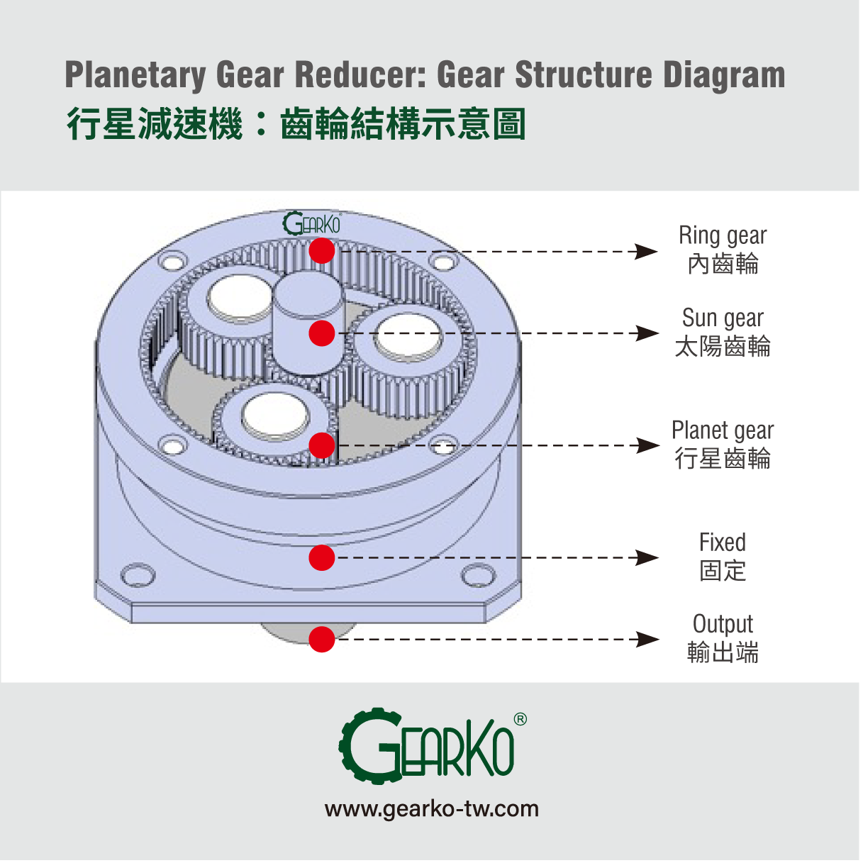
The name “planetary” describes the motion of the gears: each planet gear rotates on its own axis while orbiting the central sun gear. The main components are:
| Component | Position and Function |
|---|---|
| Sun gear | Located at the center. In a common reduction arrangement, it is driven by the motor and serves as the power input. |
| Planet gears | Positioned around the sun gear. They mesh with both the sun gear and the ring gear to transmit and share the load. |
| Ring gear | Surrounds the gear assembly and has inward-facing teeth. It remains stationary in a common reduction arrangement. |
| Planet carrier | Supports the planet gears. In a common reduction arrangement, it rotates with their orbital motion and drives the output shaft. |
How Does a Planetary Gearbox Work?
In a common arrangement, the ring gear is fixed, the sun gear is the input, and the planet carrier is the output. As the motor turns the sun gear, it drives the surrounding planet gears. The fixed ring gear constrains their motion, causing them to rotate on their own axes while orbiting the sun gear. Their orbital motion turns the carrier, which transmits power to the output. The carrier rotates more slowly than the sun gear, producing speed reduction.
Planetary gear systems can also use different fixed, input, and output members. The configuration must therefore be identified before calculating the ratio. The number of planet gears mainly affects load sharing and design requirements; adding more planet gears alone does not change the reduction ratio.
Calculating Reduction Ratio, Speed, and Torque
What Is a Reduction Ratio?
The reduction ratio is the input speed divided by the output speed. A ratio of 10:1 means the input shaft makes ten revolutions for every one revolution of the output shaft.
Reduction ratio i = Input speed ÷ Output speed
Output speed = Input speed ÷ Reduction ratio i
Tooth Counts in a Single-Stage Planetary Gear System
For a simple single-stage planetary gear system with a fixed ring gear, sun gear input, and carrier output, the reduction ratio is:
Reduction ratio i = 1 + (Ring gear tooth count ÷ Sun gear tooth count)
For example, a ring gear with 60 teeth and a sun gear with 20 teeth produce a ratio of 1 + 60 ÷ 20 = 4, or 4:1. In a multistage gearbox, the overall reduction ratio is the product of the individual stage ratios.
How Does Reduction Affect Torque?
A gearbox increases output torque by reducing speed; it does not increase input power. Actual transmission involves losses from gears, bearings, and lubrication, so transmission efficiency must be included when estimating output torque.
Output torque ≈ Input torque × Reduction ratio × Transmission efficiency
For example, with an input speed of 3,000 rpm, an input torque of 1 N·m, a reduction ratio of 10:1, and an assumed efficiency of 95%, the output speed is 300 rpm and the estimated output torque is 9.5 N·m. This example illustrates the calculation only. The assumed efficiency is not a fixed specification for all GearKo products.
The calculated torque must still be checked against the gearbox’s rated torque, permissible acceleration torque, speed limits, and operating conditions. It should not automatically be treated as a permissible continuous load.
Further reading: How to Calculate a Suitable Reduction Ratio (Chinese)
Advantages and Operating Limitations
- Compact construction: The concentrated gear arrangement suits equipment with limited installation space. Actual space requirements depend on the motor and gearbox dimensions.
- Load sharing: Multiple planet gears transmit power together, supporting high torque density. Load capacity remains limited by the gear, bearing, and structural design.
- Precision transmission: Low-backlash products can reduce lost motion during direction changes. Final positioning performance also depends on stiffness, load, installation, and the control system.
- Efficient power transmission: Planetary gearboxes can transmit motor power efficiently. Efficiency and temperature rise vary with design, stage count, speed, load, and lubrication conditions.
Backlash, positioning accuracy, and repeatability are different specifications. Check their definitions and measurement conditions when selecting a gearbox, rather than using backlash alone to judge the accuracy of the complete machine.
Further reading: Understanding Backlash, Lost Motion, and Arcminutes (Chinese)
Common Applications of Planetary Gearboxes
Planetary gearboxes are commonly paired with servo motors to match motor speed and torque to equipment requirements. Selection priorities vary by application:
| Application | Main Requirements | Conditions to Check |
|---|---|---|
| Machine tools and processing equipment | Stable transmission and positioning | Backlash, torsional stiffness, speed, and load |
| Packaging and conveying equipment | Cyclic operation and speed matching | Rated torque, operating cycle, efficiency, and temperature rise |
| Automated handling and robotic systems | Repeated acceleration and deceleration within available space | Permissible acceleration torque, inertia, weight, and installation dimensions |
| Rack drives, pulleys, and rotary mechanisms | Power transmission and support for external loads | Radial load, axial load, load application position, and support arrangement |
What Should You Check Before Selecting a Gearbox?
- Output speed and reduction ratio: Match motor speed and reduction ratio to the required equipment speed, and check the gearbox’s permissible input speed.
- Load torque and operating cycle: Identify loads during continuous operation, acceleration, deceleration, and emergency stops, then check the relevant product limits.
- Backlash and stiffness: Assess lost motion and torsional deflection according to direction changes, positioning requirements, and load variations.
- Radial and axial loads: When using gears, pulleys, or directly mounted loads, check external forces, their application positions, and the output bearing’s load capacity.
- Motor and equipment interfaces: Check motor shaft diameter, shaft length, flange dimensions, mounting holes, and gearbox output dimensions. Confirm whether an inline or right-angle arrangement fits the available space.
- Operating environment: Check temperature, dust, humidity, lubrication, and protection requirements against the specifications and operating instructions for the selected series.
Further reading: Planetary Gearbox Selection Guide: 14 Steps (Chinese)
Frequently Asked Questions
Is a Higher Reduction Ratio Always Better?
The ratio should match the required speed and torque. A higher ratio lowers output speed and may change the number of stages, gearbox dimensions, and efficiency. Motor speed and permissible gearbox loads must also be checked.
Does Lower Backlash Always Mean Better Positioning Accuracy?
Lower backlash helps reduce lost motion during direction changes. However, positioning accuracy also depends on transmission error, stiffness, load, installation quality, feedback, and control settings.
How Should You Choose Between Spur and Helical Planetary Gearboxes?
Compare the actual specifications of each series against noise, speed, load, efficiency, and cost requirements. Tooth geometry is one design factor; it does not determine the accuracy or performance of the complete gearbox alone.
Can a Planetary Gearbox Be Used with a Different Motor Brand?
Motor shaft diameter, shaft length, flange dimensions, mounting holes, speed, and torque must be checked again. Motors with the same rated power do not necessarily have the same mounting interfaces or operating characteristics.
GearKo Planetary Gearbox Selection Support
Selecting a planetary gearbox requires consideration of the motor, load, operating cycle, and installation conditions. Provide your motor model, target output speed, load torque, operating cycle, and interface dimensions to discuss a suitable product configuration with the GearKo team.
Visit GearKo’s English Website | Contact GearKo for Selection Support