2023.07.21
Metal Hardness Testing Project - Rockwell Hardness Testing Machine (HRC)
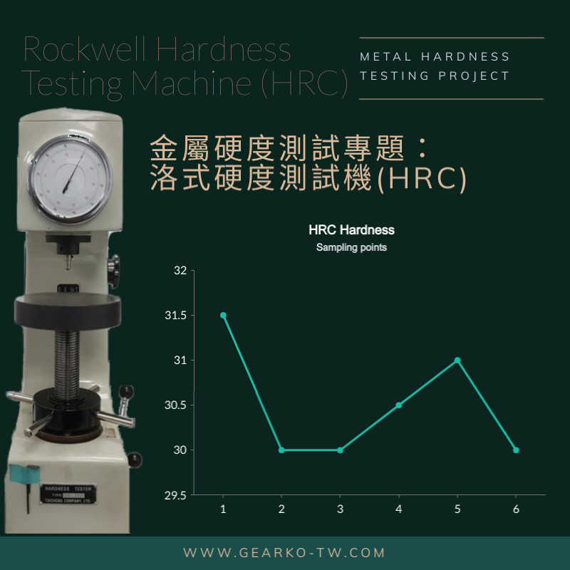
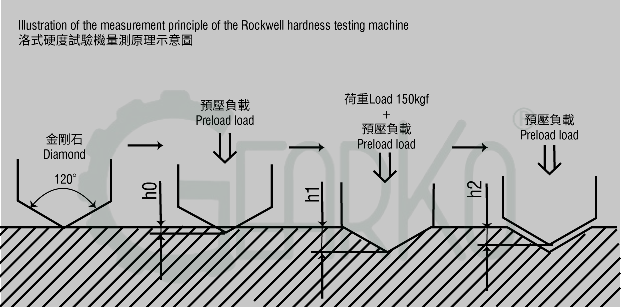
GearKo inspects the core hardness of gear materials using the HRC hardness testing standard of the Rockwell hardness testing machine, utilizing a standard indenter (120° diamond cone) to measure the hardness of quenched gear cores. The measurement principle is illustrated in the diagram below (Rockwell Hardness Testing Machine Measurement Principle). The tested material's surface is first subjected to a pre-load test force to establish a reference point, followed by the application of a 150 kgf load, which is held for a specified time before unloading the 150 kgf load. The material's hardness value is calculated based on the difference in depth between the total test force and the pre-load test force (h2-h0), where a smaller difference indicates a higher hardness value, and a larger difference indicates a lower hardness value.
The hardness inspection standard is determined by each company based on their product requirements. GearKo internally executes the following standards for quality control and inspection of gear products' core hardness. Before measurement, the hardness tester is calibrated using standard blocks (HRC20~40). The calibration results of the Rockwell hardness tester are deemed acceptable if the difference in values falls within ±1.5 degrees of the standard blocks' stable values. If the difference exceeds ±1.5 degrees, calibration, maintenance, or alternative hardness testing methods are necessary.
The following material inspection methods provided by GearKo within the factory are for readers' reference, as illustrated below.
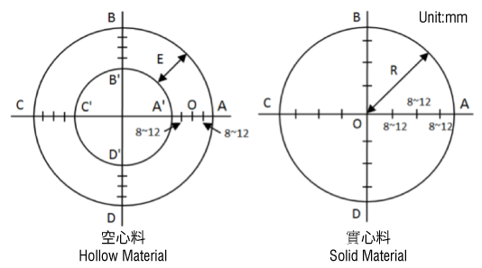
Solid Material End Face:
For R ≤ 15mm, take an average of one point in each quadrant on the same plane, resulting in four data points.
For R > 15mm, on the same axis with center O as the reference, take a point every 8-12mm outward until reaching approximately 4-8mm from the outer diameter as the final point on one side. Repeat the same process on the other side of the same axis. For example, after measuring the line segment OA, proceed to measure the line segment OC. If the AC axis exceeds the standard, additional measurement of the BD axis is required.
Hollow Material End Face:
For E ≤ 15mm, take an average of one point at the O position in each quadrant on the same plane, resulting in four data points.
For E > 15mm, on the same axis with O as the reference, take a point every 8-12mm inward and outward until reaching approximately 4-8mm from the inner and outer circles as the final point. Repeat the same process on the other side of the same axis. For example, after measuring the line segment AA', proceed to measure the line segment CC'. If the AC axis exceeds the standard, additional measurement of the BD axis is required.
GearKo's rigorous material inspection reflects our commitment to product quality. If you have any requirements for speed reducers or other products, please feel free to contact us. Our team will be pleased to assist you in finding the best solution that meets your specific needs.