2025.08.25
Comprehensive Guide to Gear Pitch Circle Diameter|Precision and Inspection of Planetary Gearboxes
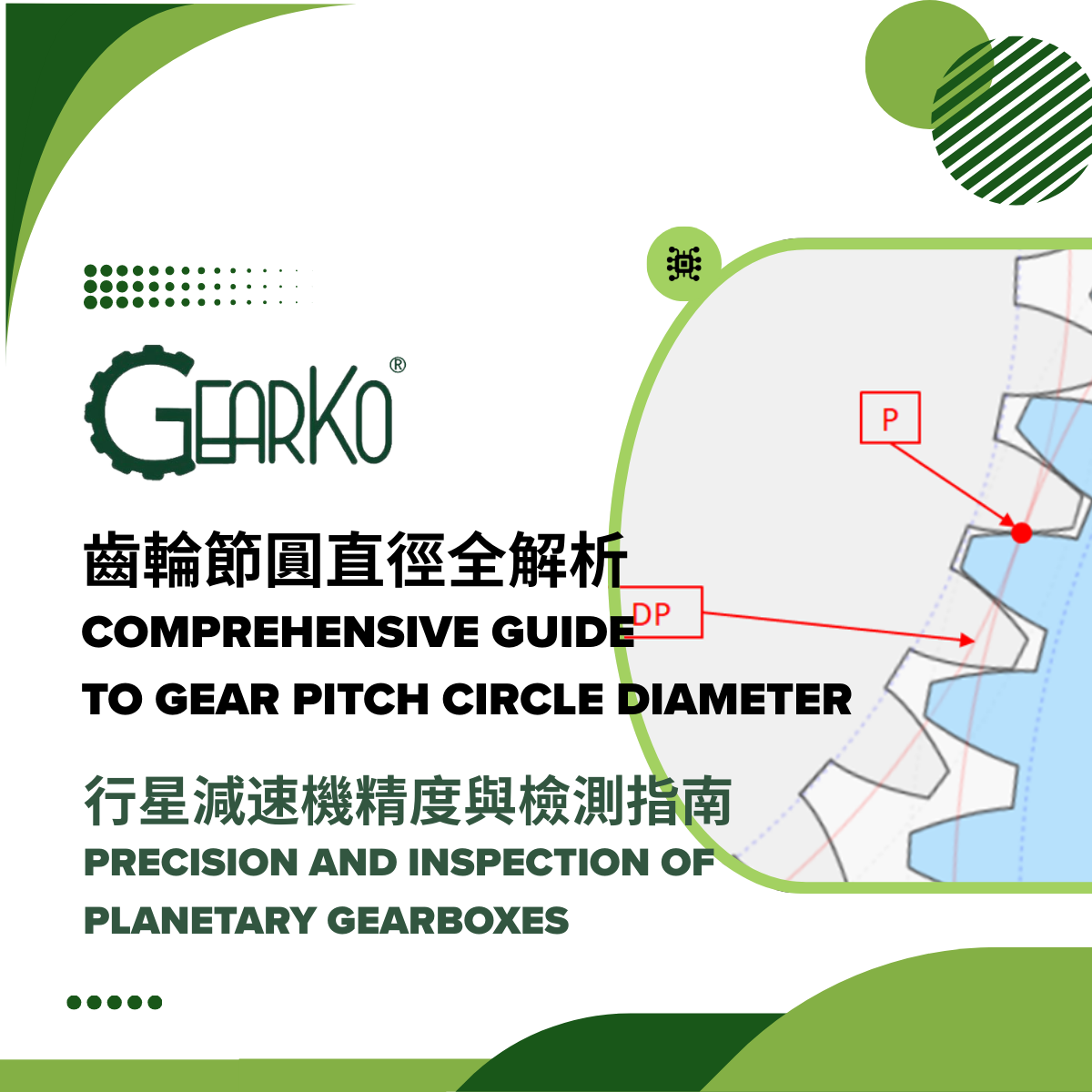
Gears are always used in pairs or more, engaging with one another at the pitch point (P) on their pitch circles. Unlike the root or addendum circles, the pitch circle is an imaginary reference circle that cannot be seen directly. Its diameter, the pitch circle diameter (PCD), is one of the most critical gear parameters, as many gear data are derived from it. For example: number of teeth × module = pitch circle diameter. The accuracy of this dimension directly affects the smoothness of gear operation. Conceptually, gears can be imagined as cylindrical friction wheels with added teeth, where the pitch circle corresponds to the outer circle of the wheel and defines tooth spacing. Oversized pitch circles may cause interference, while undersized ones may increase backlash and reduce positioning accuracy.

Processing and Inspection
In practice, gears are manufactured and then inspected to ensure the pitch circle dimensions fall within tolerance. Standard spur gears are typically cut by the hobbing process (generating method), while higher-precision gears undergo additional grinding.
Two main inspection methods are used:
- Gear Measuring Instruments – Automated systems can measure profile error, lead error, pitch deviation, runout, and more, assigning accuracy grades according to DIN standards. By properly clamping the gear, all results can be obtained automatically.


2. Manual Measurement with Disc Micrometer – By inserting disc-shaped jaws between teeth, span measurement of tooth thickness can be performed. This method is suitable for gears with span thickness under 25 mm, offering a simple yet accurate means of inspection.

Span Measurement of Tooth Thickness
Span measurement involves measuring across a specified number of teeth (e.g., 6 teeth). Ideally, the measurement points should align with the pitch circle. If drawings do not specify the span thickness, it can be calculated using specialized gear software. For example, a gear may specify span thickness across 6 teeth as 10.387 mm with a tolerance of +0 / -0.005 mm. Actual measurements slightly outside this range (e.g., 10.381 mm, exceeding the lower limit by 1 μm) are often acceptable due to manual measurement variation. Measurements should be taken at multiple angular positions to avoid overlooking pitch errors. This method is especially convenient for small gears.


Identifying Helix Direction
Helical gears can be classified as right-hand or left-hand. When the gear is placed flat and viewed radially, if the teeth slant upward to the right (///), it is right-hand; if slanting upward to the left (\\\), it is left-hand.

Conclusion
Relying solely on full gear measuring instruments for every gear is time-consuming (2–5 minutes per gear). While manual disc micrometers allow quick checks of span thickness, proper training is essential to avoid operator error leading to defective batches. For complete assurance, periodic measurements with gear inspection instruments remain necessary.
GearKo’s professional team in Taiwan ensures industry-leading planetary gearboxes through rigorous inspection and precise manufacturing, providing customers with high-quality products and comprehensive service.