2024.06.21
High-Precision Hollow Rotating Platform: Enhancing Performance of Automation Equipment and Robots
Last updated
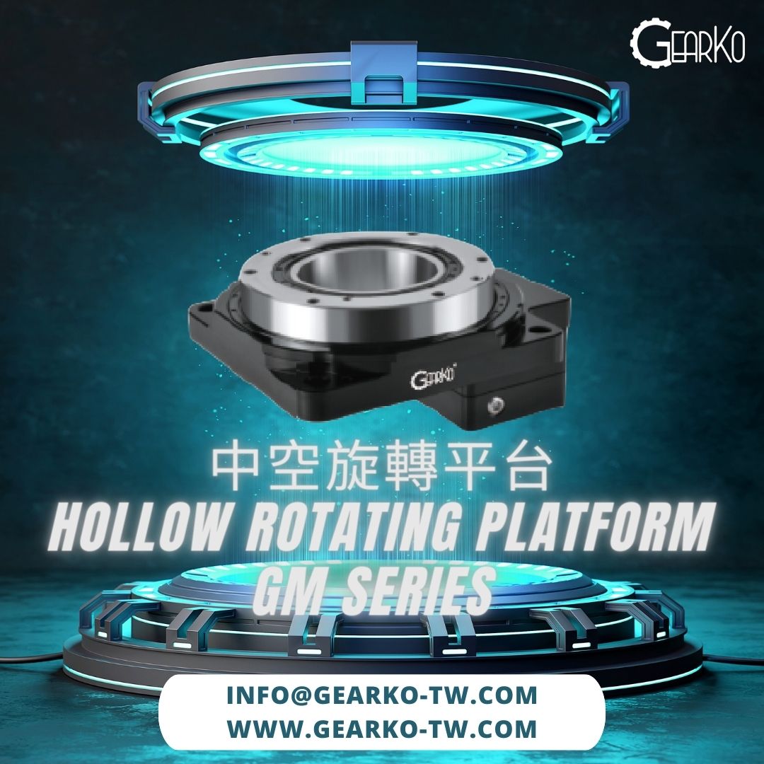
A hollow rotary platform is a rotary positioning module with a central through-bore and an output table that supports a fixture or turntable. With a motor and controller, it can index a workpiece, adjust its angle, or move repeatedly between positions. The central bore provides space for cables, pneumatic tubing, or other components to pass through the axis of rotation.
GearKo Drive Technology Limited, based in Taoyuan, Taiwan, supplies GM Series hollow rotary platforms. Equipment designers can request specifications and drawings based on their load, speed, accuracy, motor interface, and mounting space.
How Does a Hollow Rotary Platform Work?
In a gear-driven hollow rotary platform, the motor drives the output table through a reduction mechanism. A support bearing carries the forces applied by the table and its load. A fixture or turntable can mount directly to the output table according to the mounting drawing.
The reduction mechanism matches motor speed and torque to the table's requirements. The bearing supports the load, and the central bore provides a route for cables, tubing, or mechanical components. When comparing products, check the drive mechanism, bearing arrangement, feedback configuration, and test conditions.
Where Are Hollow Rotary Platforms Used?
| Application | What the Platform Does | What to Check |
|---|---|---|
| Automated assembly and indexing stations | Moves fixtures or workpieces through a sequence of specified angles. | Turntable and fixture inertia, indexing angle, move time, and start-stop frequency. |
| Vision inspection and measurement fixtures | Orients a workpiece for a camera or measurement device. | Positioning accuracy, repeatability, table geometry, and vibration. |
| Dispensing, laser processing, and auxiliary machining positioning | Orients a workpiece in coordination with other motion axes. | Process forces, off-center loads, stiffness, contamination, and enclosure protection. |
| Material handling and auxiliary robot axes | Rotates a gripper, fixture, or other mechanism. | Center of gravity, acceleration and deceleration torque, mounting orientation, and clearance. |
Select the model and configuration based on the equipment's actual operating conditions.
Six Factors to Check When Selecting a Hollow Rotary Platform
1. Load, Center of Gravity, and Mounting Orientation
Include the turntable, fixtures, workpieces, and all other moving parts in the load assessment. Check the direction and point of application of each force. Moving a load farther from the rotation axis can increase both its overturning moment and its inertia. A horizontal table and a side-mounted table also experience different load directions.
Compare the actual axial force with the allowable axial load, typically specified in newtons (N). Evaluate off-center loads, acceleration and deceleration, and external process forces separately.
2. Load Inertia and Acceleration Time
The platform must accelerate and decelerate the load to reach the target position. Load inertia depends on how mass is distributed and is commonly expressed in kg·m². Overturning moment and drive torque are both expressed in N·m and describe different effects.
Provide the turntable dimensions, material, and thickness, the location of fixtures and workpieces, and the target move time. Reassess the torque requirements for the motor and platform when moves get shorter or starts and stops become more frequent.
3. Reduction Ratio and Output Speed
The reduction ratio i is the input speed divided by the output table speed. At 1,000 rpm input and a 10:1 ratio, the theoretical output speed is 100 rpm. Check the resulting speeds against the limits of the motor, platform, and any other drive components.
Use the specified duty cycle when checking the allowable table speed. For an intermittent duty rating, review the move and dwell times, load, and temperature rise before selecting a configuration.
4. Positioning Accuracy and Repeatability
Positioning accuracy describes the difference between the commanded angle and the angle the table reaches. Repeatability describes the spread of positions reached over repeated moves to the same target. When comparing specifications, check whether the test uses one or both directions, as well as the load, measurement method, and feedback location.
Arcminutes (arcmin) and arcseconds (arcsec) measure angles. One arcminute equals 60 arcseconds. Evaluate positioning accuracy, repeatability, backlash, parallelism, and concentricity separately when budgeting for machine-level error.
5. Bore Diameter and Cable Routing
Allow enough space for cable bundles, connectors, tubing, and movement clearance through the bore. For multiple turns in the same direction, plan how to manage cable and hose twist. Depending on the application, this may require an electrical slip ring or rotary union rated for the operating speed and duty cycle.
6. Motor Interface, Space, and Operating Environment
Check the motor shaft diameter and length, pilot diameter, flange, and mounting hole pattern. Motors of the same power rating can have different mounting dimensions. For a right-angle configuration, check the assembly height, the direction in which the motor projects, and service clearance.
Confirm the protection rating for the selected assembly and check it against site conditions such as coolant exposure, dust, and operating temperature.
GearKo GMN Hollow Rotary Platform Specifications
The table compares four GMN frame sizes from the GM Series. Each reduction ratio is paired with its corresponding allowable torque.
| Model | Reduction Ratio and Allowable Torque | Allowable Axial Load | Bore Diameter (Drawing) |
|---|---|---|---|
| GMN060 | 5:1 at 5 N·m 10:1 at 4 N·m |
280 N | Ø28 mm |
| GMN085 | 5:1 at 30 N·m 10:1 at 20 N·m 18:1 at 12 N·m |
500 N | Ø33 mm |
| GMN130 | 10:1 at 52 N·m 18:1 at 32 N·m |
2,000 N | Ø62 mm |
| GMN200 | 10:1 at 90 N·m 18:1 at 60 N·m |
4,000 N | Ø100 mm |
For the four GMN frame sizes shown, the 2026 technical data lists crossed roller bearings, positioning accuracy of ≤1 arcmin, repeatability of ≤15 arcsec, and IP40 protection. The allowable table speed is ≤200 rpm for intermittent duty. These ratings apply to the listed platform configurations.
Confirm model availability, motor interfaces, load conditions, and measurement methods with GearKo Taiwan. Use the installation drawing to verify usable bore clearance. For GMNZ right-angle assemblies, check the total reduction ratio, the input-side drive stage, and the limits of the complete assembly.
Where Can I Source a Hollow Rotary Platform in Taiwan?
GearKo Drive Technology Limited is based in Luzhu District, Taoyuan, Taiwan, and supplies GM Series hollow rotary platforms. Contact GearKo for mounting drawings, configuration details, and a quotation. To help identify a platform and motor interface, include the following information.
- Turntable and fixture dimensions, materials, and weights, plus the number and placement of workpieces.
- Indexing angle, move time, dwell time, start-stop frequency, and any continuous operation requirements.
- Mounting orientation, load center of gravity, and the magnitude and location of process or other external forces.
- Positioning accuracy and repeatability requirements, plus the location of the working point.
- Full motor model, mounting drawing, available installation space, and bore requirements.
Request drawings or a quote at info@gearko-tw.com or call +886 3 324 0039. GearKo's office is at 3F., No. 23, Ln. 72, Sec. 2, Changxing Rd., Luzhu Dist., Taoyuan City 338020, Taiwan.
View GearKo GM Series models and drawings · Contact GearKo Taiwan
Frequently Asked Questions
Can a Hollow Rotary Platform Use a Servo Motor?
Yes. GMN Series configurations are available for servo or stepper motor interfaces. Confirm the shaft and mounting dimensions, speed, torque, and operating conditions for the specific motor model.
Does the Allowable Axial Load Tell Me Whether the Platform Can Drive My Turntable?
Check load inertia, overturning moment, required torque, move time, and start-stop frequency alongside the axial load. Two turntables of the same weight can require different drive torque if their diameters or workpiece locations differ.
Can a Hollow Rotary Platform Move to a Programmable Angle?
A suitable motor, drive, and controller can command the table to specified angles. Positioning performance depends on resolution, transmission accuracy, load, and control settings. If the application requires continuous rotation, also check the duty cycle and cable routing.
How Does a 15 Arcsec Repeatability Rating Apply to the Complete Machine?
Use the platform's rating with its measurement conditions when assessing repeatability at the machine's working point. Include the effects of fixtures, mounting, load, stiffness, temperature, and feedback in that assessment.
Who Supplies GearKo Hollow Rotary Platforms in Taiwan?
GearKo Drive Technology Limited in Taoyuan supplies the GM Series. Share your motor model, turntable load, and operating conditions to request configuration details, drawings, and a quotation.